Creating class diagrams with UML
Class diagrams are structure diagrams within the Unified Modeling Language, or UML for short. The modeling language UML is an ISO standard. It illustrates systems of object-orientated programming. Business processes can also be recorded clearly with UML. Using visual means, UML shows system states and describes interactions between system elements. The notation defines shapes and lines for 14 diagram types.
Class diagrams in the context of the Unified Modeling Language
Metamodeling describes both individual elements of the modeling language and the language itself. It defines language units for different levels. For example, a unit of speech in this visual language is behaviour. It describes both a metaclass and a generic term for all dynamic factors within a system. Another language unit is the object, the basic element of the object-orientated programming. UML class diagrams model objects in stances of classes. Therefore, the class diagram is one of the most important and commonly used diagram types in UML.
The diagram types are divided into two main categories according to their function: structure diagrams and behavioural diagrams. The latter have a subcategory, called interaction diagrams. These do not just model the general behaviuor of a system, but also focus on information flows between objects over time in a process. These include, for example, sequence diagrams, which model the chronological order of messages that flow in a detailed use case. Behavioural diagrams visualise dynamic processes. An example is the activity diagram. This shows how individual actions interact in a process flow. Structural diagrams, on the other hand, show static states; they illustrate the elements of a system and their interdependencies.
The class diagram assigns object instances to specific classes based on their properties – there is a hierarchical dependency. At the same time, relationships exist between different classes or between objects.
UML class diagrams: fields of application
Class diagrams represent states with system elements. They show structures down to the smallest instance. Therefore, they are suitable for representing detailed software architectures. Concrete programming steps can be derived from this. Some software-based programming environments convert these UML diagrams directly into code frames. Using team sharing, developers communicate with each other or with other decision-makers within a company. For outsiders, a UML diagram provides an overview of planned system structures or process flows. It can also be used to formulate system requirements that the developers then implement. IT professionals can model, and effectively modify diagrams without having to program larger environments or processes in the planning phase.
These are the areas of application for a class diagram:
- They describe types within a system. The graphic representation can be transferred to different programming languages and environments. It therefore exists independently of the future application.
- You model existing software architectures. If additional components are to be integrated, they visualise suitable structures on which new components can be installed. For future system elements, class diagrams create a guide to the program code. Depending on requirements, this step can be sketchy or very detailed.
- They represent data models. They are suitable for systems of varying complexity.
- For nested applications, documentation and maintenance can become very complex. Class diagrams provide an overview of the scheme.
- They represent requirements for software. They can easily be forwarded as image files through internal business channels. They enable experts from different departments to exchange ideas about the architecture.
- The UML standard uses class diagrams to visualise its own notation.
Class diagrams: notation according to UML
UML class diagrams consist of classes and their instances (objects) as well as interfaces. They create hierarchical relationships and associations between those elements. The notation used in this diagram type is the basic building block for most other structure diagrams. UML 2 defines structure diagrams as classifiers. Within UML metamodeling, package diagrams, component diagrams, and the like are subclasses of the structure diagram. Other diagrams in this category use class diagram modified building blocks for their notation.
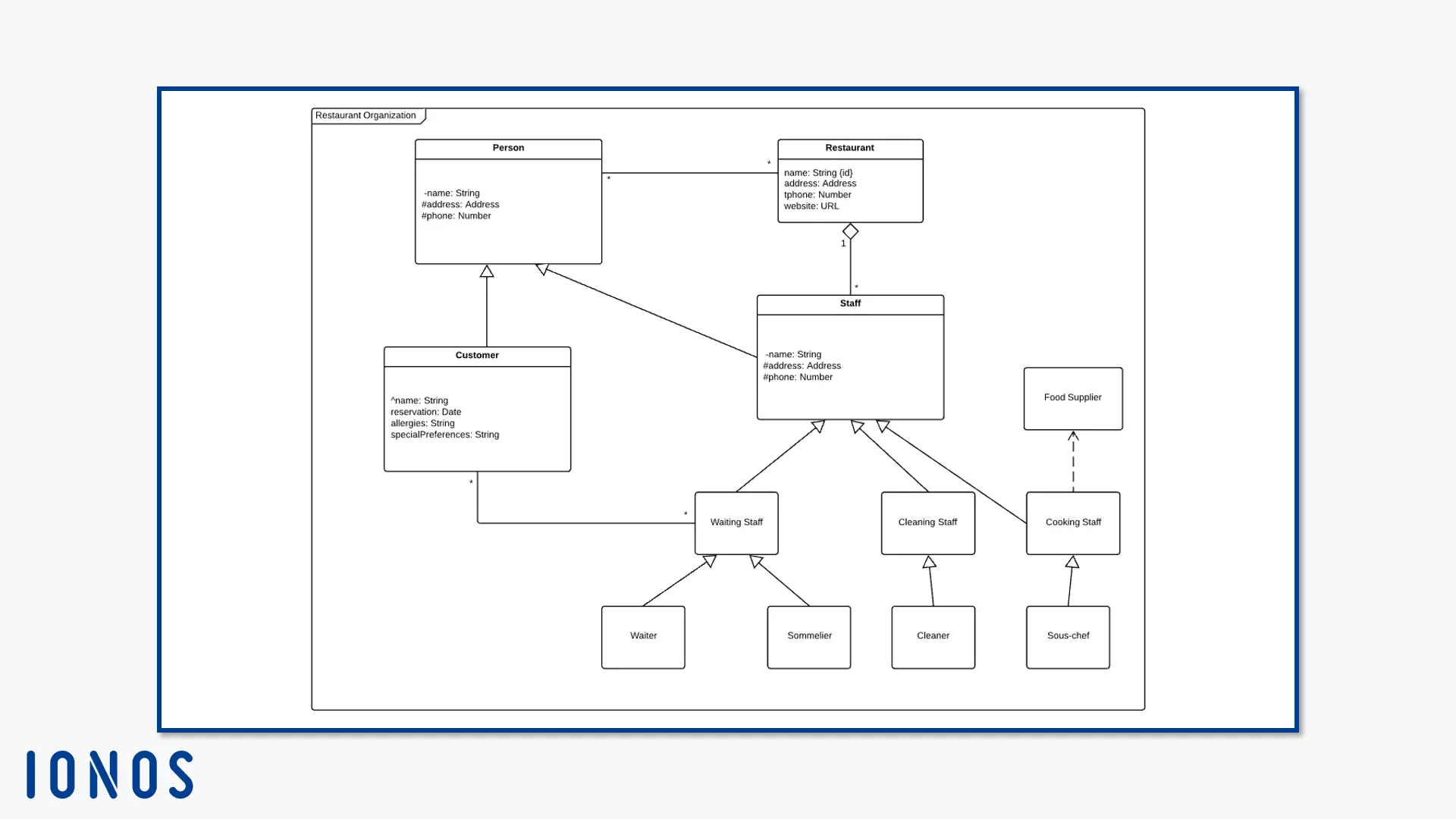
As a classifier, UML understands an abstract metaclass. It is used to assign model elements within the modeling language to a common concept. It’s called generalisation. In this way, the standard can be formulated in general terms. If the specification refers to a certain element, just this special feature needs to be explained.
The class
The class is a model element in the class diagram, and is a specialisation of the EncapsulatedClassifier and the BehaviouredClassifier. It summarises a set of instances. Object instances within a class have the same characteristics (attributes) and behaviours (methods). They also have the same semantics, i.e. they use the same characters with the same meaning. This makes the class a kind of pattern for its objects. It instantiates the objects and defines their behaviour in the system.
The instance is a concrete instance of an abstract element. It performs a prescribed behaviour within the specified parameters. Some instances explicitly name UML. Therefore, the object is a named instance of the class. Instance properties are modelled with diagrams at instance level. Instead of a class diagram, draw an object diagram, for example.
Encapsulated classifiers extend structured classifiers. The latter are characterised by the fact that they can prescribe a structure inside and incorporate connected elements. These elements (metaclass: ConnectableElements) influence the behaviour of classifiers. Each linked element represents a participant in the classifiers’ behaviour. They also play their own role. The encapsulated classifier also has a docking point (port). This isolates the classifier from the system without losing the connection.
Behaviour classifiers often have a connection to an interface, InterfaceRealisation. The classifier implicity complies with the interface conditions by supporting the interface’s functionality. You draw the InterfaceRealisation (also called “Lollipop”) as an empty circle, which is connected to the class by a line.
These metaclasses classify objects. The class is the specific characteristic of these metaclasses. In this way, it clarifies the classification and specifies the individual components that make up the structure and behaviour of these objects. Classes have properties that describe them (and their subordinate objects). These include:
- Characteristics (properties or attributes, if they belong to the class)
- Operations (operations can be accessed for an object)
- Receptions since UML 2.0
- Ports since UML 2.0
- Connectors
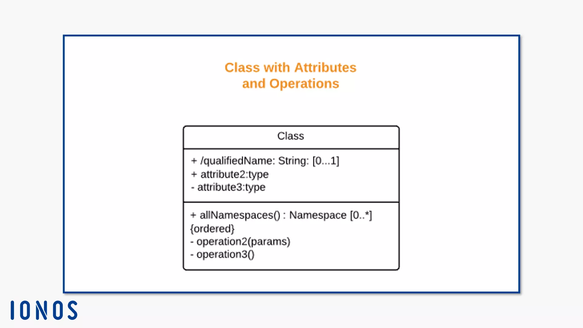
These properties are included in the notation when you create a class diagram. In UML, a class is displayed as a rectangle with a solid line. The body consists of three compartments arranged one above the other. Only the upper most part needs to be modelled, because this is where you specify the class name. You can also optionally label the other two partitions with attributes (middle) and operations (bottom). You assign different visibilities to these elements by writing the following symbols in front of their names:
- + =public
- - = private
- # = protected
- / = derived
- ~ = packet
- * = haphazard
Properties (characteristics)
Properties are connected elements. Class attributes (ownedAttributes) are always roles. They are joined by connectors. If they have the property isComposite=true, they are class parts.
The UML property is a structural feature that has various areas of application. In addition to its function as a class attribute, it can also display sent association.
The property type is derived from the classifier’s name. You can also define a default value for a characteristic. Modifiers also specify how a characteristic behaves:
- Ordered (Notation: isOrdered = true)
- Unique (Notation: isUnique = true)
- Not unique (Notation: isUnique = false)
- Read-only (The characteristic can only be read, notation: isReadOnly = true)
- Sequence (The characteristic is an ordered collection, notation: isUnique = false and isOrdered = true)
- Union (a derived subset union, notation: union)
- ID (Belongs to the classifier’s name, notation: id)
- Characteristic limitation (a delimitation that influences the characteristic, notation: property-constraint)
- Redefinition of a characteristic (redefines an inherited, renamed characteristic, notation: redefines [Characteristicname])
- Characteristic subset (symbolises a characteristic that is a subset of a named characteristic, notation: subsets [Characteristicname])
Operations
Operations are behavioural functions. They occur in classes, but also in data types or interfaces. You access a class instance directly. The operation defines the following aspects of an access call:
- Name
- Type
- Parameter
- Restrictions
The operation belongs to its higher-level classifier. This may change them by redefining type or parameters.
There are preconditions for operations. These must be fulfilled before the operation can be executed. However, UML does not define how a behaviour access call turns out if the preconditions are not fulfilled. You also define subsequent conditions that must be fulfilled when the operation is completed. Body conditions limit the output result to a value calculated from their specifications. This value should meet the post-conditions. However, the operation can also raise an exception whilst it is being executed. Subsequently, it probably does not meet the post-conditions.
The notation for the class diagram stipulates that operations in a compartment are noted in the class body. According to the UML standard, this information is mandatory. At the same time, UML allows you to suppress all standard specifications within a class. Only the name needs to be noted down.
Signal receiver
A signal receiver indicates that a classifier is ready to accept a signal. It also defines which types of signals the instances of the class accept. The signal receiver is named like its signal. Write down the corresponding details in the class body, in a compartment under the operations.
Ports
Ports are connections for encapsulated classifiers. They represent a point at which the classifier interacts with its environment. Apart from the ports, the encapsulated classifier is a self-contained system. Since its internal structure and behaviour elements remain unaffected by the rest of the system, you can also define this classifier independently. As long as a system meets the port restrictions, you can reuse the encapsulated classifier in different environments.
UMI also allows multiple docking points per classifier. You can define separate rules for each port. The port is a property of the classifier, so you define its rules in the properties area. These include the services that the classifier offers to its environment and the services it needs. You differentiate between different information flows by identifying the port used for this.
Ports themselves also have properties. If the port executes published classifier functions, this indicates the isService property. If isService = true is given, the port is an indispensable part of the encapsulated classifiers’ externally visible functions. With isService = false, the port is not one of the essential features and can subsequently be changed or deleted, like other internal functions.
Ports interact with interfaces. There are provided and required interfaces (see “Interfaces” below). The interface connected to the port specifies the interactions that run over the port. Since the docking site is a property, it has a type. The value of isConjugated mediates between the type and the port’s interface. If the value is true, the required interface can be derived directly from the type of port or from the set of interfaces that the port implements. In this case, an interface provided is derived from the number of interfaces. If isConjugated is true, the provided interface is the right type.
When an encapsulated classifier generates an instance, corresponding instances are created for each of its ports. A port holds the instance in accordance with its type and its multiplicity (see below). The instances are called UML interaction points. Each instance has unique references that distinguish it from the different requests for behavioural functions directed to its ports.
When an encapsulated classifier generates an instance, corresponding instances are then created for each of its ports. A port holds the instance in accordance with its type and multiplicity (see below). The instances are called UML interaction points. Each instance has unique references that distinguish it from the different requests for behavioural functions directed to its ports.
Ports with property isBehaviour = true sends a request to the encapsulated classifier’s instance. The request adopts the instance’s specified behaviour. This means that the behaviour ports do not direct queries into your classifier’s interior. If no behaviour is defined in the class diagram, messages on these ports will be lost.
You can model a port as a small square on the frame of the classifier it belongs to. Draw the required or provided interface to the port. If you do not specify any special characteristics for the port, draw the interface without a port.
Connectors
Connectors define connections between two or more instances. The specification enables their communication. Unlike relationships like associations, connectors do not connect just any instances, just instances that are defined as connection parts. Connectors are modelled as edges with at least two ends. They represent the participating instances that assign a type to the linkable elements.
Multiplicities
Another important factor is multiplicity. This parameter specifies how many instances a structured class can form. It also limits attributes and operations. It is a part of the inner structure – this is a mandatory element in the class body. You enter it behind the attributes and operations. This section also includes the topology. Nodes (object instances) connect to topology networks through communication paths (CommunicationPaths).
Multiplicities are noted as follows:
<multiplicity> : <multiplicityrangeh> [<ordername> , <unqieidentifierr>]
The multiplicity range specifies a fixed value or a range:
- 0 = The class does not form instances (rarely occurs)
- 0..1 = Either no instance or an instance
- 1 or 1..1 = Exactly one instance
- 0..* or only * = No instance or more with open value
- 1..* = One instance or more with open value
The order and unique-ness can be expressed as a set or by single terms, separated by commas. Depending on whether the nodes are unique or ordered in the set, the set is given a type description. In the notation, describe the individual sises as ordered/unordered or unique/not unique.
| Quantity type | Unique | Ordered |
|---|---|---|
| Sequence | No | Yes |
| Multi-quantity (bag) | No | No |
| Ordered quantity | Yes | Yes |
| Quantity | Yes | No |
Constraints
Constraints should also be mentioned here. In earlier UML versions, the constraint belonged to relationships. UML now defines the restriction as a packable element. This means that it can belong directly to a package. It also enters into relationships with other elements, like classes or characteristics, for example. However, this does not affect the notation. This limitation is a condition or assurance to its owner. It can affect one or more elements.
The owning element needs access to the restriction. It checks whether the restriction is valid and whether it has been fulfilled. It depends on the owner when this happens. Some elements (like the operation) verify before, during and/or after execution. They have preconditions, body conditions, and postconditions. UML calls the specification of when an element checks its restriction a context. The latter describes which elements define the restriction, which aspect it evaluates and which result it expects. A constraint gets its exact specification from a Boolean value specification.
The notation consists of a text chain in the following form:
<Name of the restricted element> ::= { <Name of the restriction> : <Boolean expression> }
UML does not prescribe a language. You can choose which restrictions you want to make in which language when you create your class diagram. Use a programming language like Java, a natural language or a machine-readable language like XML. The Object Management Group that sets the UML standard publishes the Object Constraint Language (OCL). This language defines UML-compatible restrictions. Its advantage is that it fits seamlessly into the notation.
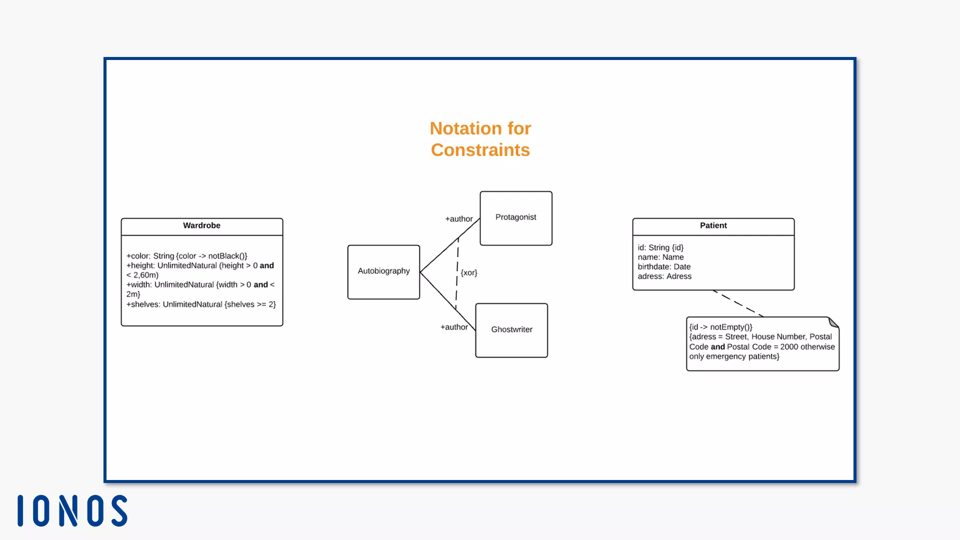
You note some restricted elements in UML as text, for example, an attribute of a class in the class diagram. Note the restriction behind the text element in braces. If the owner is an element that you represent as a symbol, place the restriction as close as possible to the symbol; it should be obvious that both elements have a semantic relationship. Make the connection even clearer by writing the restriction in a notepad symbol and connecting it to its owner through a dashed line.
If the restriction affects two elements, connect the owners using a dashed line. Write the restriction in curly brackets. If you place an arrowhead at one end, this signals the position of the owner within a collection of constrained elements (constrainedElements). The arrow points away from the first position to the second. If more than two items have the constraint, use the memo icon and link each item to the constraint.
Edges are also amongst the elements that can be limited. Model more than two edges of the same type, drag the dashed constraint line through all edges that represent the elements involved.
Stereotypes
Stereotypes define metaclass extensions. According to the UML specification, they belong to the profiles. If a stereotype describes additional properties of several metaclasses, it can only describe one metaclass instance at a time during runtime. Amongst the metaclasses, stereotypes play a role, since they can never stand alone. Stereotypes are always modelled with the classifier it enhances. You link the metaclass to the stereotype by modeling an extension.
Since UML 2.4 defines the specification: the label of a stereotype is written with a capital letter at the beginning, like <<Type>> for example. Other labels, like properties at associations ends, are written in lowercase throughout.
There are two types of relationships between (meta) class and stereotype. The required extension (notation: isRequired = true) defines that a stereotype connects to each instance of the metaclass in the class diagram. The extension (notation: isRequired = false) allows you to freely link instances of the metaclass to a stereotype. You can also delete the stereotype. However, a particular instance may only be linked to a particular stereotype once during runtime.
If you want to remove a stereotype, delete the profile that defines it from the applied profile (appliedprofiles) area of the parent package. Alternatively, delete the instance it enhances.
UML defines some class stereotypes that extend your UML class diagrams. Six stereotypes are standard. Three stereotypes are often used, but not standardised, and you can use them to convert the pattern “Model Presentation Control” (MVC) into UML. The three non-standard stereotypes are:
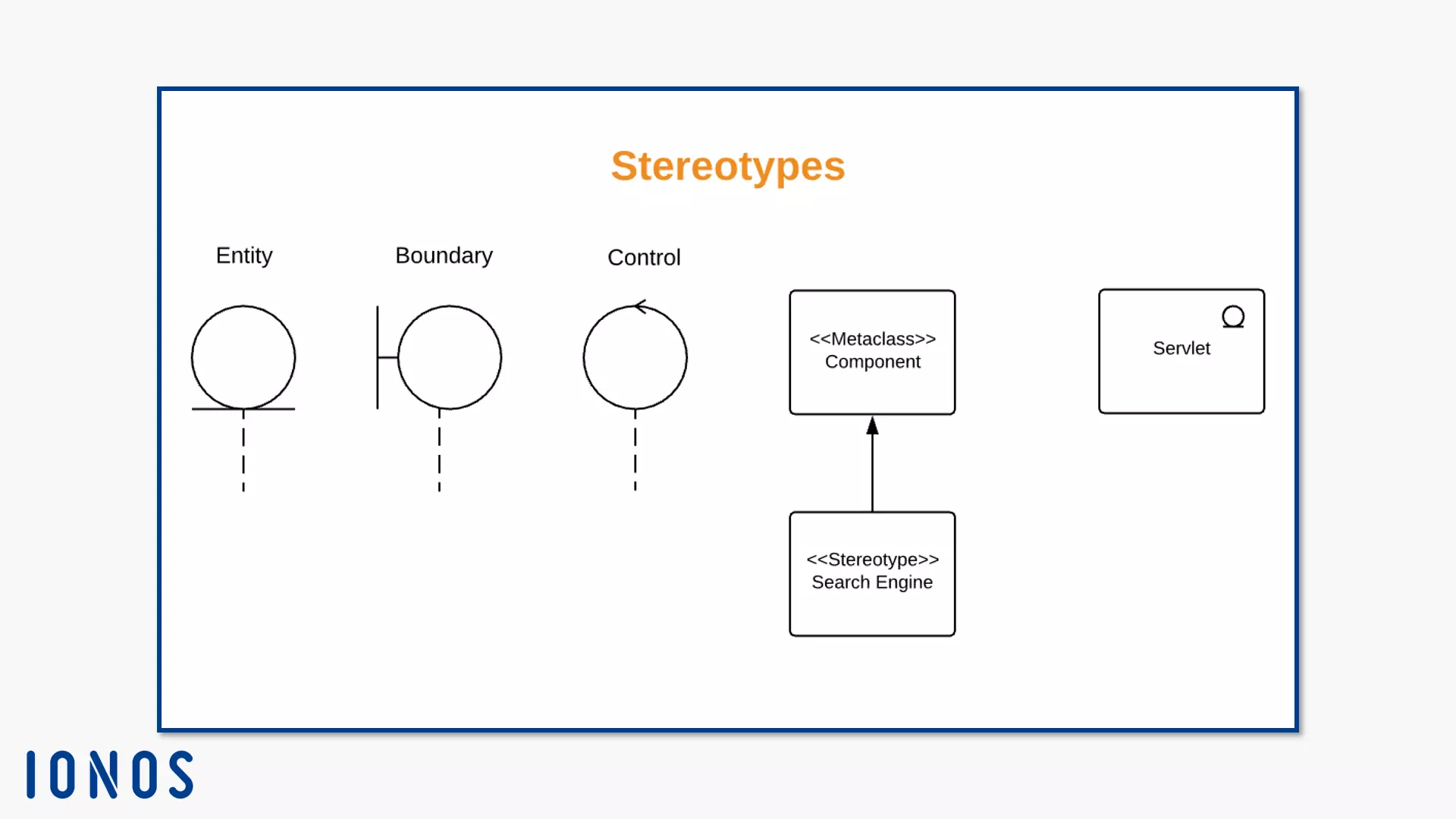
- The entity (notation: <<Entity>>): The stereotype Entity defines a class or an object. The respective instance represents a collection of data. It is often system data that needs to be stored over a longer time. The entity assumes the role of the model from the MVC pattern. UML knows this stereotype, but assigns it to component diagrams by default. The frequently used notation does not list the specification. They model the entity as a circle resting on a short line.
- The boundary (notation: <<Boundary>>): The boundary is a stereotype for a class or object. It roughly corresponds to the element view in the MVC pattern. The boundary models the boundary of your system, e.g. a user interface. Usually they are represented as a circle with a line on the left that meets a vertical line.
- The control element (notation: <<Control>>): The control element represents the same elements as the controller under MVC. Classes or objects with this stereotype model elements that coordinate system behaviour or control flows. In the UML standard, the stereotype <<Focus>> performs similar tasks. You draw a control instance as a circle with an open arrowhead on the line.
These three stereotypes can also be drawn as a simple class. Note the name of the stereotype in the rectangle. Modellers mainly use these shapes in sequence diagrams. If you want to know more about entity boundary control diagrams, read our article about UML sequence diagrams.
These standardised stereotypes are suitable for class diagrams:
- Focus (<<Focus>>)
- Helper (<<Auxiliary>>)
- Type (<<Type>>)
- Implementation class (<<ImplementationClass>>)
- Metaclass (<<Metaclass>>)
- Utility (<<Utility>>)
Focus
The focus class defines the basic business logic or control flow of helper classes. These support the focus class that binds one or more helpers. It implicitly defines supporting classes by entering into a dependency relationship with them (see “The Directed Relationship” below). If it uses helper classes, it defines them explicitly. The UML standard recommends this stereotype especially for the design phase when you represent control flows between components or define the basic business logic.
Business logic, also known as application logic, describes the logic of a system that deals with the execution of real business requirements. It differs from the logic that dictates the technical execution. In object-orientated programming, business logic brought out the concept of the business object. This models concrete processes and real values in an information system.
Helper
The helper class usually acts in combination with the focus class. It generally supports classes of crucial importance to the system. To this end, it carries out secondary control flows and defines subsidiary logic. It the helper class supports a focus class, the definition is explicit. You implicitly define the supported class during a dependency relationship.
Type
The type class defines an area for business objects. It also specifies the object operators. The type stereotype can have attributes and associations. However, it does not describe the physical execution of the object.
Application class
Some programming languages (e.g. Java or C++) only allow one class for each instance. However, you can use UML to assign an instance to several classes. The application class builds a bridge between these two worlds. This stereotype limits the UML class. It determines that an instance below it can only realise one class. The application class can implement several different types. To successfully execute a classifier assigned to it, it must fulfill two conditions: it must provide all classifier operations and these must have classifier behaviour defined. However, physical attributes and associations do not have to match.
Metaclass
Since the forms of class and metaclass are not different, the metaclass label indicates that it is the stereotype metaclass. The instances of this class are themselves classes. With this stereotype, you work at a higher level of abstraction.
Utility
The utility class has no instances. It merely identifies a collection of named attributes and operations. These are always static. Static attributes do not change when they are called. Static operations are used for collateral entities or entity types. If you use the utility class, you first need to specify the corresponding values and operations right from the start, since these no longer change. Underlining indicates these elements.
UML specifies further standard stereotypes for other diagram types. Their application areas and notation can be found in UML specification 2.5.1, chapter 22: Standard profiles, table 22.1, page 680.
Gateways
Interfaces are classifiers. In their notation, they resemble the classes. In contrast to the class, however, they are declarations, i.e. they declare a set of logically-related public functions and obligations. They use a contract for this. If an instance executes the interface, it must fulfill this contract. This means that the instance offers a service according to the contract. As a declaration, the interface itself does not form any instances.
This is where the class comes in, because it instantiates. Your instance uses interface specifications. To do this, the interface contract must be fulfilled. In return, it uses the interface as a public backdrop. In addition, a classifier can use several interfaces. Conversely, an interface is also used by several classifiers. In the UML class diagram, the notations of the interface and class are similar: a rectangle, optionally with three areas separated by lines.
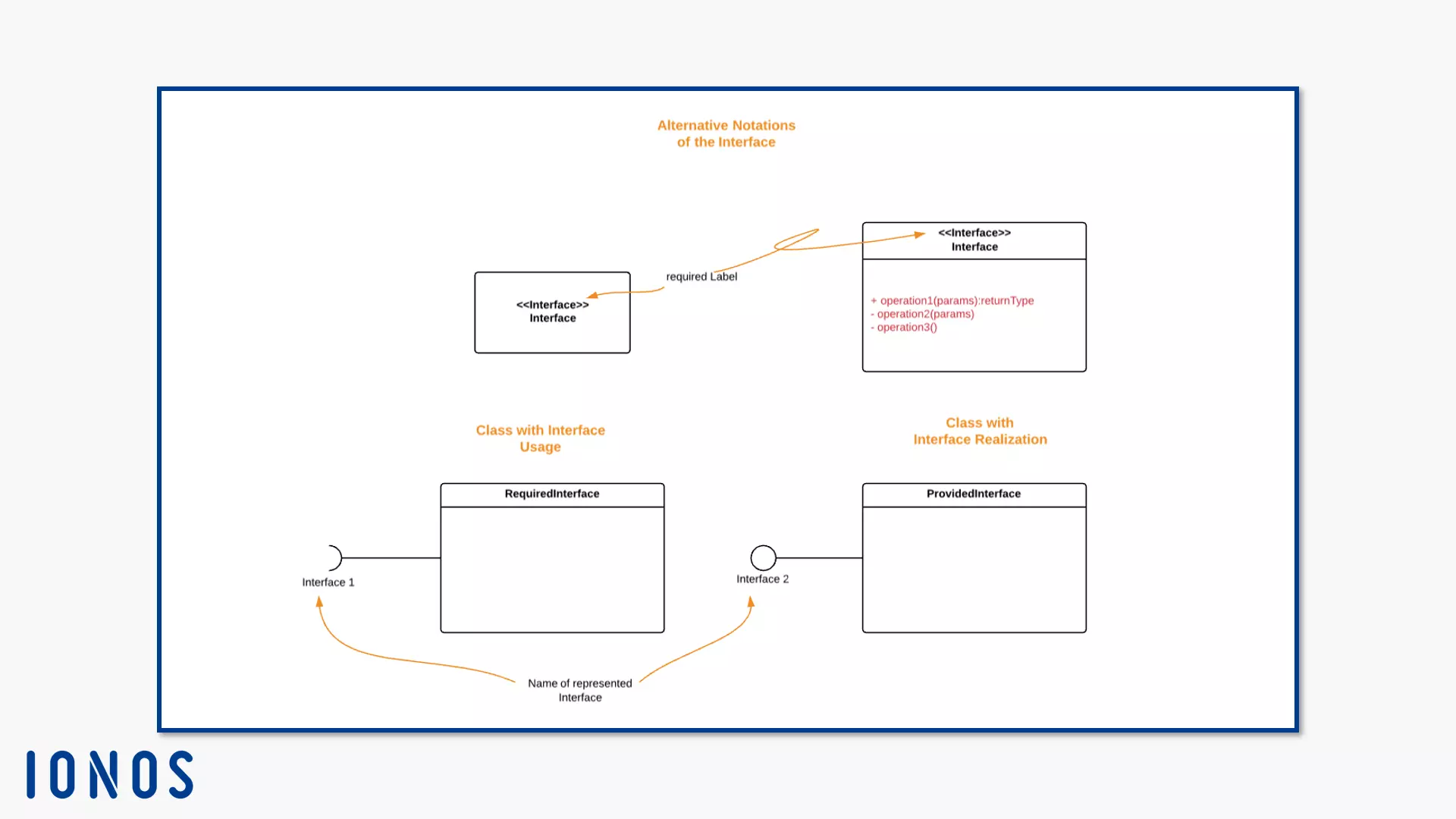
To show that a class uses an interface, you use the notation InterfaceRealisation (already known from the behaviour classifiers). This represents a provided interface, an interface that executes an instance directly. If the class has a public port, it provides the interface. You display InterfaceRealisation with a circle that is connected to the classifier by a line.
There are also required interfaces. You visualise a dependency relationship (see “Relationships” below). An element needs another element to perform the full scope of its own functions. In this case, a classifier (or one of its instances) requires an interface. The InterfaceUsage specifies the requirements for this interface. A solid line connects the classifier with an open semicircle. This symbolises the interface. Note the name of the interface for both representatives under the (semicircle).
If a class inherits an interface to a subordinate class, model the interface connection to the subordinate class or instance. Show the hierarchical relationship with a circumflex (^), e.g. ^Interface 1.
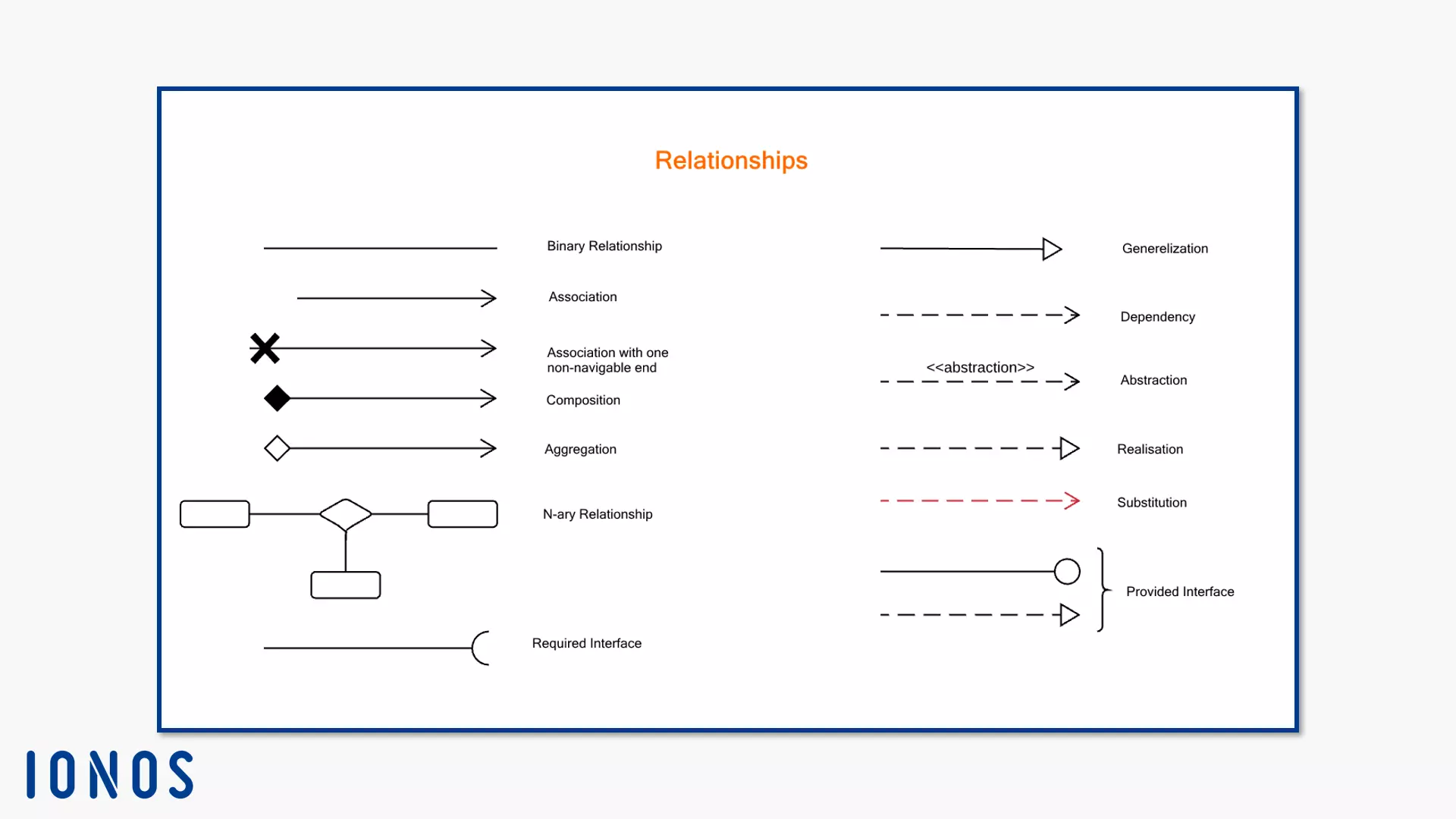
Use the rectangular interface notation, draw an edge between the two nodes. In the class diagram, edges model the relationships between classes, instances, or components. UML prescribes different lines and arrows for different functions and relationships. In this case, you connect a class to the required interface using a dashed arrow with an open tip. Give the arrow the label <<use>>. You connect a provided interface to a class using a dotted arrow with a closed, unfilled tip. The arrow always points in the direction of the interface.
Data types
Data types combine a set of objects with their operations. They use concrete value ranges and merge them with their special operations. Objects can have several types. Their numerical values range from primitive types to longer enumerations.
Data types are classifiers. You identify your instances only by their value. Use data types to visualise value types, primitive types and structured types in the UML class diagram. If you copy a data type instance or model two instances of the same data type with the same value, these instances are considered identical.
If the data type has attributes, UML classifies it as a structured data type. Its instances are only considered the same if their structure and the values of their attributes are the same.
Primitive types do not have a subordinate structure, but stand for atomic data values. They are also used in the class diagram for restrictions. Most of these types have complex semantics outside the UML specification. In UML, however, they have no identity, which is why they are indistinguishable for the same value. These are some primitive types in UML:
- Boolean (Boolean variables)
- Integer (whole numbers)
- UnlimitedNatural (unlimited, natural number)
- Real (real numbers)
- String (character chain)
They note primitive types with the label <<primitive>> above the name of the respective data type.
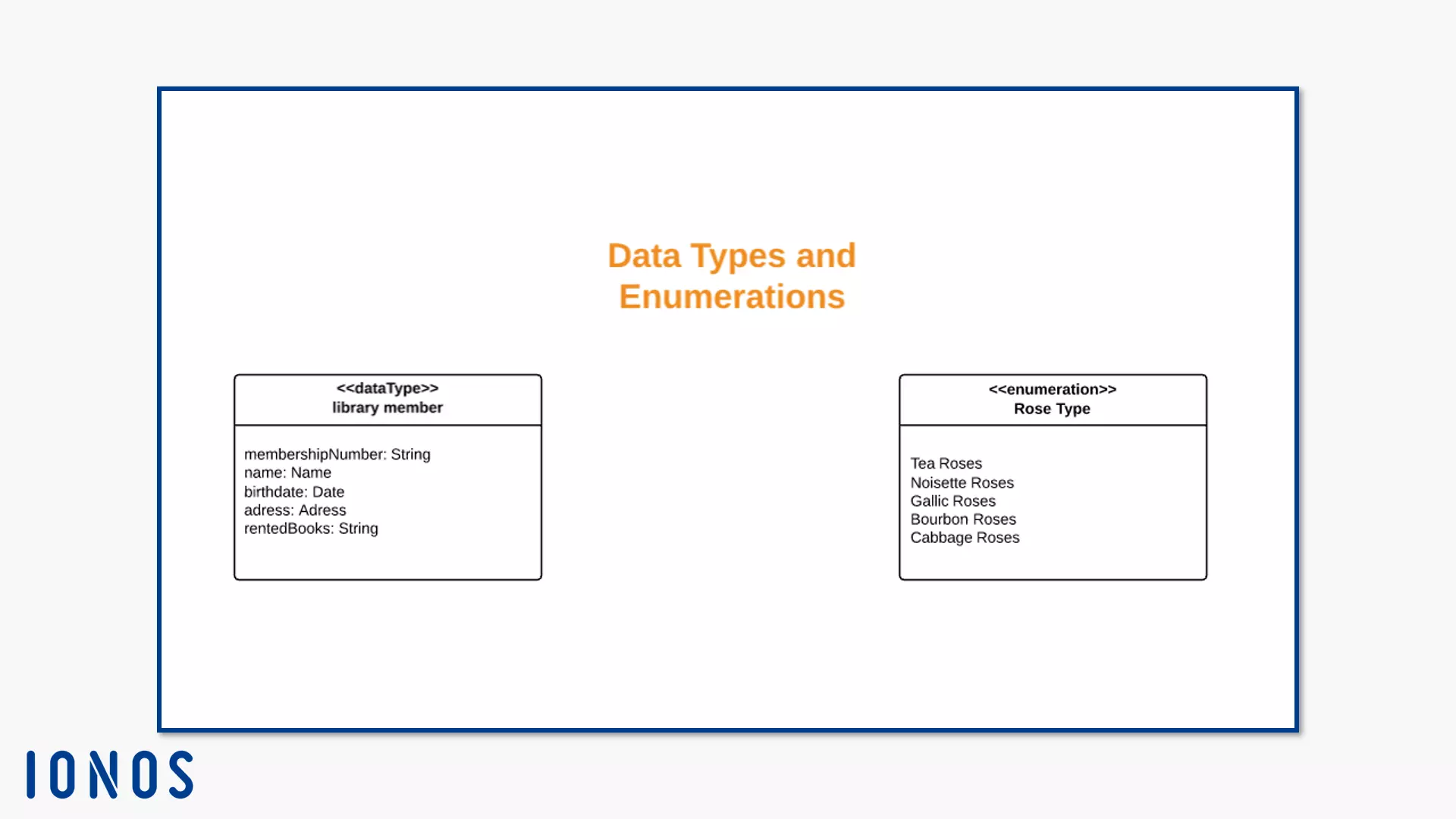
The enumeration is a data type. They represent the value of the enumeration as a so-called enumeration letter symbol. As you can see in the picture above, it is simply a name that symbolises a certain value. You choose this yourself. In the “Types of Roses” list, for example, the name “Tea Roses” stands for the number of tea roses in a florist’s assortment. In the class diagram, draw this classifier with the symbol for the class, a rectangle. The name and the label <<enumeration>> are in the header. They separate the head area from the body by horizontal lines in departments.
As with other classes, the enumeration reserves the upper sections for attributes and operations. If they remained empty, omit both sections from the diagram. In the bottom part, enter your bullet symbols. For example, the enumeration of rose species in a florist consists of the head with the title “Rose species” and the body with a list: tea roses, noisette roses, gallica roses, bourbon roses, cinnamon roses.
Relationships
Class diagrams represent relationships between system elements. The viewer should see which components the system needs and how they influence each other. The UML element relationship is an abstract class. It stands for the idea of a relationship between system components. Thus, this element has no separate notation. However, its characteristics have specific details that distinguish them.
Relationships are understood in UML as edges between nodes. Therefore, you generally model relationships with a line or variations thereof – like the arrow.
The UML definition for relationship subclasses and instances has changed drastically from UML 1 to UML 2. Originally, for example, there were semantic, structural, and directional relationships. UML assigned three concrete relationships (association, restriction, and dependence) to the semantic relationships. Under UML 2, restrictions are now packable elements, associations define some sources as structural and semantic relationships. This dependency now runs under directional relationships.
It remains to be seen how the standard will change in future versions. In the following, we continue to explain class diagrams according to UML 2.5, so the metaclass relationship has two subclasses: the directed relationship and the association.
The association
The association is a relationship that connects tuples. In computer science, tuples are ordered collections of values. In contrast to the quantity, the logical connection and sequence play a role. Therefore, it is not wrong to assign a structural component to the association in addition to its official designation as a semantic relationship. The association is a connection between classifiers. The elements in this relationship have a logical or physical proximity. Depending on the number of members, the association is called binary (two instances), ternary (three instances) or n-är (from four instances).
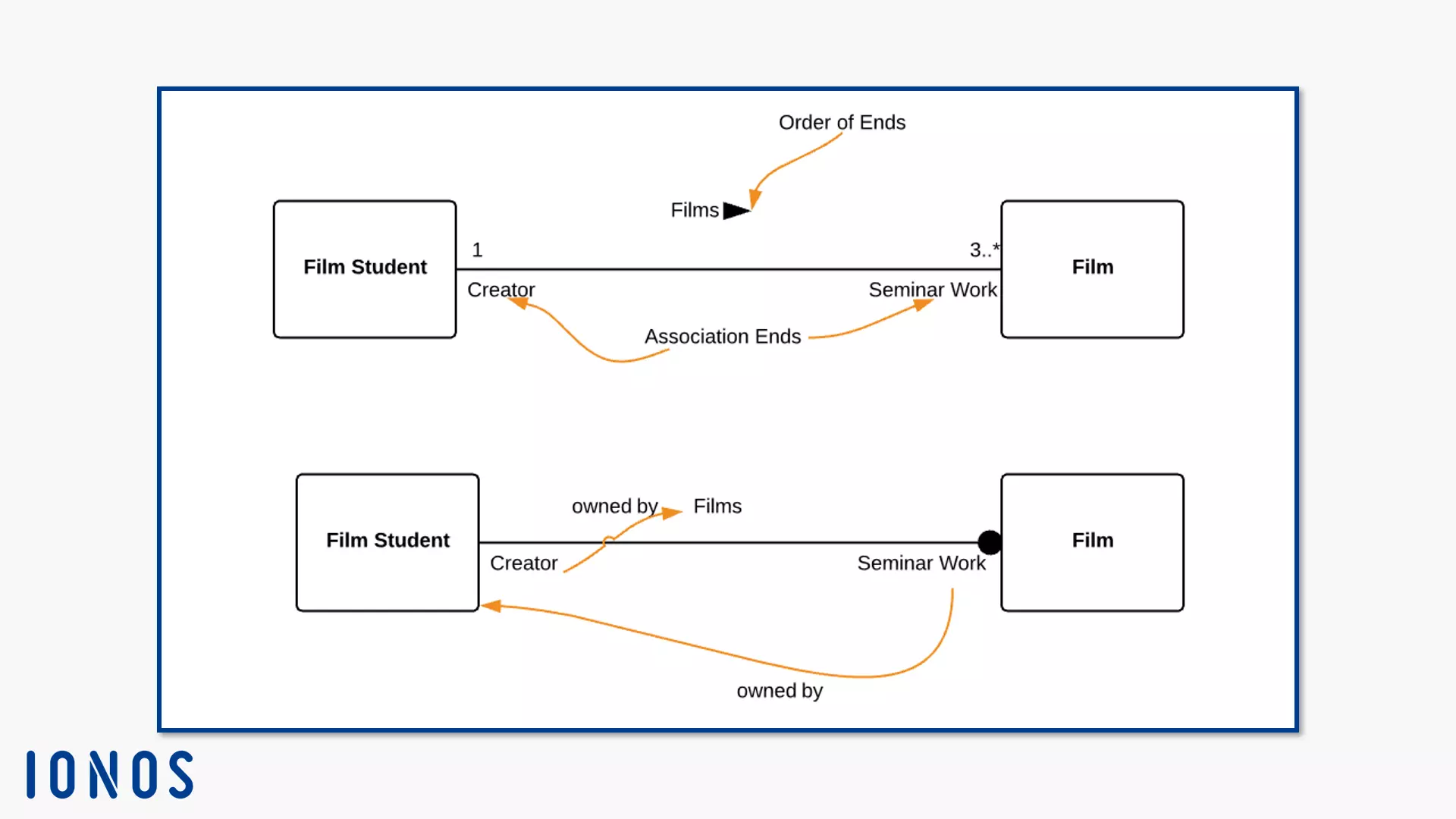
Association sending connects associations with instances in the UML class diagram. The end of the association has an end name. This name expresses the role of the instance in the respective relationship. Let’s say a student makes several versions of a short film for a film seminar. The role of the film would then be “seminar work.” You write the name under the link line, in each case to the instance symbol that describes it. The end belongs to either the association itself or the end classifier. For more than two ends, the role belongs to the association.
The arrow next to the association name in the upper class diagram indicates the direction of the relationship. In the lower diagram, the point at the “Film” instance indicates that the association end “seminar paper” belongs to the “film student” instance. Since the end of the association “Creator” doesn’t have this mark, it belongs to the association itself. The multiplicity “1” indicates that exactly one instance “film student” exists. The “Film” instance has at least three training courses.
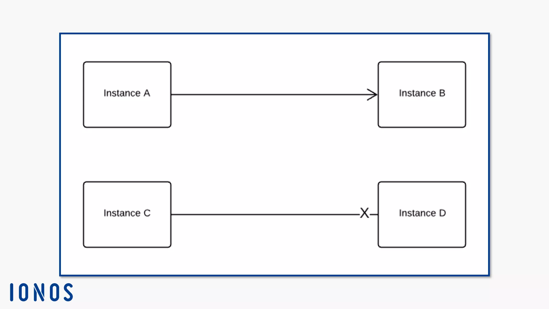
Navigability is an End Property. It indicates whether an instance is accessible at this end of the association from the other end of the association. If instance B can be reached by instance A, draw an open arrowhead on the association edge in the direction of instance B directly to the instance symbol B. If instance D cannot be reached by instance C, draw an X on the line for instance D. If you don’t want to specify navigability, do not draw a separate notation.
There are two association variants: the link and the aggregation.
- The link is an association instance. It has at least two ends, each of which has a multiplicity. This value must be an instance of the ends data type. In our example image above, a film student films three films during their studies. The value for the “Student” instance is “1.” The value for the “Movie” instance is “3.” You model he connection as solid lines between relationship participants. In contrast to associations, the link connects instances and not classifiers.
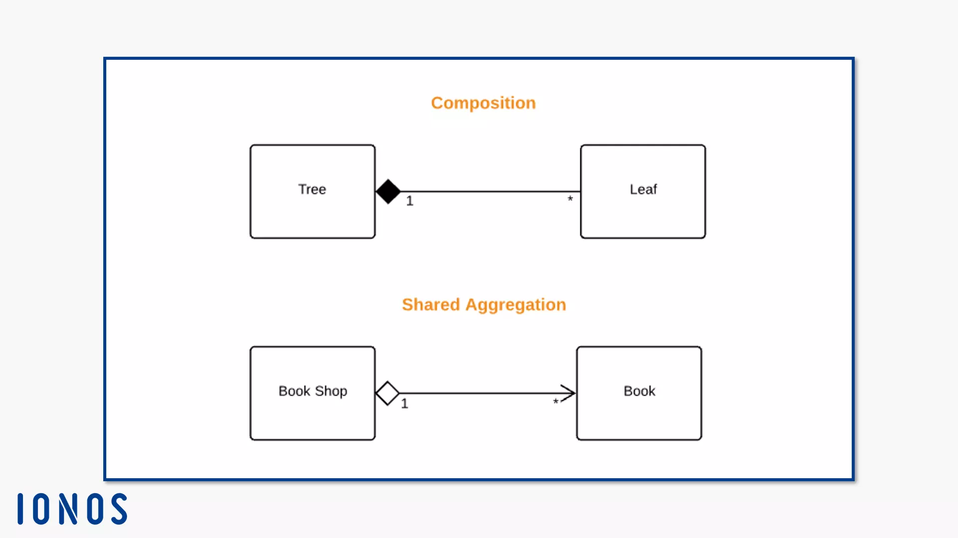
- Aggregation is a binary association. This means that it always has two participants. Unlike the link, it does not create relationships at the same level. Instead, it shows relationships between a part and the whole. You represent the aggregation with a property at the end of the association. They model a rhombus on the instance that represents the whole.
The subtype composition (composite aggregation) describes the relationship between a composition of parts and a single part thereof. If the system deletes the whole (the composition), it also destroys the individual part. For example, if a tree is the whole then a leaf is part of it. If the tree falls victim to a forest fire, the fire also destroys the leaves. For example, if you create a class diagram and represent this relationship, draw a solid line between the instances. Model a black-filled rhombus on the composition side (in the example: the “tree” instance). This page is also called the end of aggregation.
The second subtype of aggregation is shared aggregation (or just aggregation for short). This asymmetric relationship exists between a property and an instance that represents a set of instances. The connection should be direct. Otherwise, a composition instance could be interpreted as part of itself. This can happen if you model the dependency relationship cyclically. The shared property can belong to several compositions. At the same time, their instance can exist independently of the composition. If the system deletes a composition (or all of them) in this case, the sub-instance can continue to exist. Therefore, this relationship is considered weak in comparison to composition.
The association also offers a special feature: the association class. It is both the class and the relationship. This allows you to assign attributes to the association class in the class diagram.
The directed relationship
The directional relationship is an abstract class. It describes relationships between a source and a target. Both ends of the relationship can have several elements. Like the association, the directed relationship also has no fixed notation. Their subclasses create specific forms. These are based on a line from the source to the target. The following instances define a directional relationship:
- Generalisation
- Dependency
- Template binding
- Include: belongs to the notation for use case diagrams
- Extend: belongs to the notation for use case diagrams
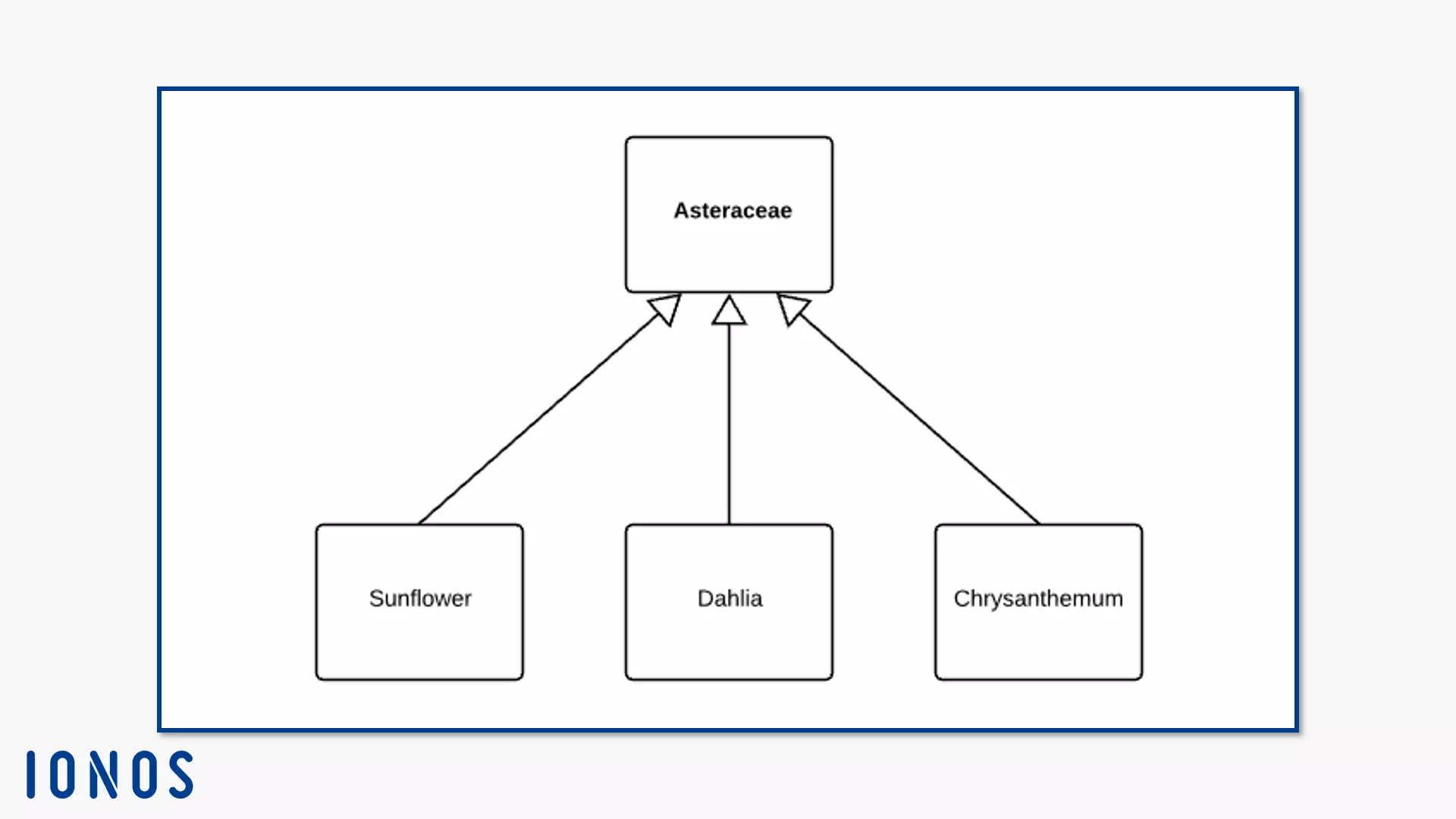
Generalisation is a binary relationship between classes. It goes from a subclass to a superclass – that is, from a specific to a more general class. The particular class (e.g. dahlia) has the generalisation. An arrow with close but unfilled arrowhead points from this source to the target. The goal is the general class (e.g. daisy).
The subclass specifies the general class. This also means that the subclass shares some properties – in content and structure – with the superclass, usually the basic elements. This circumstance is called inheritance. In this example, the dahlia class shares the capitulum-shaped inflorescence with the superclass daisy. A specific feature of the genus dahlia are its eight pairs of chromosomes – other plants usually have just two pairs of chromosomes. The different dahlia species therefore form more diverse characteristics.
Generalisations are also called “is a…” relationships. This is because one can say “A dahlia is a composite.”
Implicitly, UML allows a multiple inheritance. This allows you to model several subclasses that have both common and different superclasses. Alternatively, there are several levels of generalisation. You can either display these relationships with the arrow notation or you interlace the subclasses within their superclasses. To do this, you model all associated subclasses in the superclasses’ body.
The Generalisation Set helps you to keep track of the class diagram. The set is a packable element. Packages in UML are containers for named elements that have semantic similarities and may change together. A package is namespace, not a class. However, you can associate the generalisation set with a classifier. This one is called a power type.
You model the power type as a string a the generalisation edge like this: {[isCovering Property] , [isDisjoint Property]} : [Powertyps name]. The isCovering property describes whether the set is complete. The values are either complete or incomplete. The isDisjoint property indicates whether the classifiers share common instances. The values are either disjoint (no overlapping) or overlapping.
The standardisation UML 2.5 gives little information about inheritance. However, they can be based on previous versions. UML 2 generally explains that specialised classes adopt the characteristics and restrictions of their superclasses. UML 1.4 specialised that declared attributes in a subclass overwrite inherited attributes.
Dependency is a relationship between “provider” and “client” (supplier-client-relationship). This directional relationship describes that an element is dependent on another element. It can also be a set of elements. The client needs another element for the more detailed specification or to perform their tasks. Without the provider, the client lacks a structural or semantic component. Therefore, changes in the provider may have an impact on the client. According to UML 2.5, semantics always affects the named element, but not its instances. Dependencies play a role, not just in the UML class diagram, but also in other structural diagrams like the component diagram or the provision diagram.
The dependency has three categories:
- Abstraction
- Deployment
- Usage
the right, the directed relationships.]
Abstraction connects elements on different levels. Alternatively, it shows different perspectives. The named elements in this dependency relationship represent the same concept. The more specific element according to the UML standard is the client, which depends on the provider, the more abstract element. So the end of the arrow should be in the subclass and the top in the superclass. UML also allows an inverse notation. If you think it makes more sense for the abstract element to depend on its subclass, draw the arrowhead to the more specific element.
Abstraction has two subclasses: realisation and manifestation.
We have already mentioned realisation with regard to interfaces. InterfaceRealisation is a specification of the realisation. It describes a relationship between classifier and interface. The classifier uses the interface to offer their client a service. The interface executes this service. To do this, the classifier must fulfill the contract that the interface specifies. The notation for provided and requires interfaces can be found in the “Interfaces” section.
Substitution is another relationship that specifies the realisation. It consists of a substitute classifier and a contract classifier. The substitute classifier fulfils the contract of the other classifier. During runtime, instances of the replacement classifier potentially replace instances of the contract classifier. In contrast to specialisation, there is no structural similarity between elements of substitution. You note the substitution as a dependency edge (dashed arrow with open tip) in the class diagram and add the keyword <<substitute>> to the edge.
The specification describes a relationship between an artifact and one of more model elements. UML defines artifacts as classifiers. They symbolise concrete, physical instances like archive folders. The characteristic value means that an artifact executes a connected element directly. Conversely, it can symbolise that elements are involved in the artifact’s creation. The characteristic value is an element of the staging diagram and is only mentioned here for the sake of completeness. They require the same notation as replacements. The keyword is <<manifest>>.
Abstraction also defines some stereotypes. Stereotypes belong to the UML profiles. If you want to extend an existing metaclass for a project, you define a profile for it. The stereotype class is always used together with the metaclass, since a profile only changes what already exists or adds a terminology. Since UML 2.4.1, UML notes stereotypes with capital letters at the beginning. The standard stereotypes for abstraction are:
- <<Derive>>: An element is derived from another element. Usually they are of the same type.
- <<Refine>>: An element gives more detailed information for a class that also exists in the other element. The elements are on different levels of abstraction. For example, an executive model refines its “Employees” class in relation to the “Employees” class at the design level.
- <<Trace>>: Different models express different aspects of a system. Mapping or tracing allows you to trace elements that represent the same concept in different models. You can use the trace to understand changes being made to elements and specifications.
Use these abstraction stereotypes to map the relationship between client and provider. This process can be bilateral or one-sided and formal or informal. Client and provider are in different diagrams, e.g. in a class diagram and in an application case diagram.
Deployment shows the relationship between an artifact and its target. In the UML diagram, the deployment target is indicated by the deployment edge of one or more artifacts. The keyword for the edge is <<deploy>>. You can also apply this dependency at instance level. Alternatively, model the artifact into the target’s body. To do this, either record the artifact as a symbol or list the artifacts provided. This dependency is part of the notation for delivery diagrams.
Usage describes a relationship in which the client needs the provider to complete their tasks or perform operations. The usage therefore implements the general dependency as an instance. This dependence characterises some concrete relationships:
- <<use>>: One element uses another element, but the exact relationship between participants and the exact benefits are not specified in detail.
- <<create>>: A client classifier is one of its structural or behavioural elements creates one or more instances of the vendor classifier.
- <<call>>: One operation calls another operation. The target can be any operation in the environment of the source operation, including superordinate classifiers.
- <<send>>: An operation is the source, the client. Your target is a signal. The dependency models that the operation sends the target signal.
- (Required Interface -----C): Unlike the interface provided, the required interface does not exist in the classifier. It determines the services that a classifier needs to perform its functions for its client. The dependency exists between classifier and interface. Read more about this in the “Interfaces” section.
Template binding is the last directional relationship used in the class diagram. When you create a class diagram, it is often helpful to create templates for your classes. For classes, templates consist of template parameters. These parameters belong in the template signature. The signature determines the ordered set of parameters within the template. If you model classes that do not have to have individual properties, you work more efficiently when you use templates. However, if you want a class to have fixed parameters, use the template binding. The relationship exists between a bound element and the template signature in a target template.
The bound element is template capable, i.e. it can either become a template on its own or it can be bound to other templates. The element is bound because it has a link to a template. This link describes the structure of the element by replacing formal template parameters from the template with valuable parameters.
Summary
The class diagram is one of the most popular UML diagrams because it displays system structures both in detail and clearly arranged. The system displays the structure diagram in the static state. This gives viewers an overview of the necessary elements in a system. You also represent relationships between the building blocks of your system architecture. From real objects to abstract classes with extending profiles, you can use the UML class diagram to model independently of the programming language. This promotes understanding between departments when a project is being implemented.


